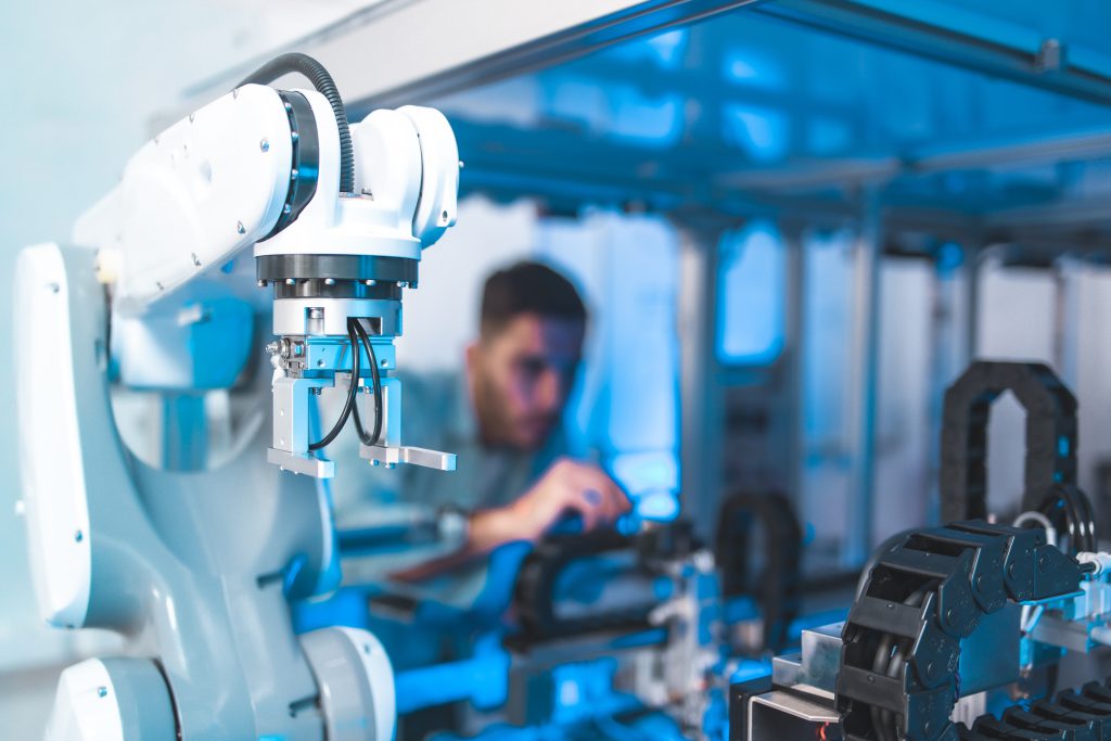
How Pneumatic Actuators Work: The Core Principle
A pneumatic actuator converts the potential energy stored in compressed air into mechanical motion, either linear or rotary, that can push, pull, clamp, or rotate a load. Understanding the pneumatic actuator working principle starts with a simple relationship: force is proportional to the air pressure applied and the surface area it acts on. When compressed air enters a sealed chamber, it pushes against a piston, and that push translates into a controlled, repeatable stroke.
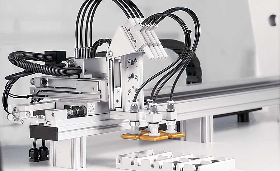
This is why pneumatic actuators are so common in industrial automation — the same basic principle scales from a small gripper finger to a heavy-duty clamping cylinder, simply by changing bore size, stroke length, or operating pressure. The actuator itself doesn’t generate energy; it converts energy that’s already been compressed and stored elsewhere in the system, which is one of the reasons pneumatic systems tend to be simple, durable, and easy to maintain compared to some electromechanical alternatives.
Pneumatic Actuator Operation: Inside the Cylinder
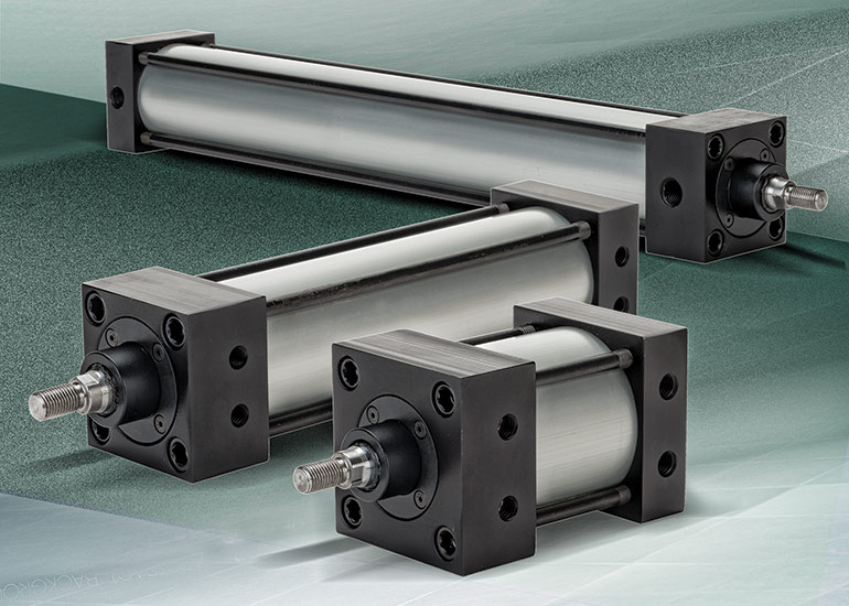
At the core of pneumatic actuator operation is the cylinder assembly: a barrel, a piston, a piston rod, and a set of seals that keep compressed air from leaking between chambers. Air enters through a port on one side of the piston, and as pressure builds, it forces the piston, and the rod attached to it, to move along the bore.
Seals play a quieter but equally important role in pneumatic cylinder operation. Piston seals prevent air from bypassing between the two chambers, while rod seals keep contaminants out and lubrication in as the rod extends and retracts. Cushioning, often built into the end caps, slows the piston down just before it reaches full stroke, which reduces mechanical shock and extends the actuator’s working life.
None of this is particularly complex on its own, which is part of the appeal: a pneumatic actuator mechanism has relatively few moving parts, so there’s less that can fail compared to more intricate drive systems.
Single-Acting vs. Double-Acting Pneumatic Actuators
The clearest distinction in how pneumatic actuators work comes down to how they return to their starting position. A single-acting pneumatic actuator uses compressed air to move in one direction only, typically extending the rod, and relies on a mechanical spring to push it back once the air pressure is released. This makes single-acting cylinders simpler and often more compact, but the spring reduces the usable force output and adds a bit of resistance the system has to work against.
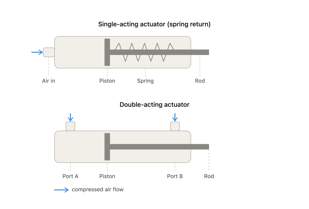
A double-acting pneumatic actuator, by contrast, uses compressed air on both sides of the piston: one port extends the rod, the other retracts it. This gives full force in both directions and generally allows for more precise control over speed and positioning, which is why double-acting cylinders are the more common choice in applications that need consistent force on the return stroke as well as the forward one.
Neither type is universally better — the right choice depends on load, cycle speed, and available space. For a fuller breakdown of actuator types and where each one fits, see What Is a Pneumatic Actuator? Types & Applications.
Compressed Air Actuator Operation: The Role of Valves
A pneumatic actuator never works in isolation — a compressed air actuator only moves when a directional control valve tells it to. The valve routes air to one chamber while opening the opposite chamber to exhaust, and reversing that flow is what reverses the actuator’s stroke. Solenoid-operated valves are the most common way to do this automatically, switching air flow in response to an electrical signal from a controller or PLC.
Flow control valves, usually mounted directly on the cylinder ports, regulate how quickly air can enter or exit each chamber, which is often the simplest way to adjust stroke speed without changing the actuator itself. Selecting the right combination of actuator and pneumatic valves has a direct effect on cycle time, smoothness of motion, and how much wear the system accumulates over time.
Pneumatic Motion Control Systems: Actuators Working Together
An actuator is only one component of a broader pneumatic motion control system, which typically also includes valves, air preparation equipment, sensors, and a controller that sequences everything. In a well-designed pneumatic motion control system, the actuator’s role is narrow and specific: convert a signal into a precise, repeatable mechanical movement, while the rest of the system handles timing, safety interlocks, and feedback.
This is also where system-level decisions, such as tubing size, filtration, and pressure regulation, end up affecting actuator performance just as much as the cylinder specification does. For guidance on how these pieces fit together, see Best Practices for Designing a Pneumatic Control System.
Pneumatic Actuators in Canadian Manufacturing
Pneumatic actuators remain a practical, cost-effective choice across Canada’s manufacturing base, particularly in Ontario, which hosts one of North America’s largest concentrations of automotive assembly and parts manufacturing alongside strong food and beverage processing and electronics assembly sectors. These industries depend on repeatable, high-cycle motion — exactly what pneumatic actuators are built for — whether that’s clamping a part during welding, indexing a conveyor, or operating a pick-and-place station.
Humphrey Automation supports manufacturers across Ontario, Ottawa, and Montreal with actuators from AirTAC, Fabco-Air, and Koganei, covering everything from compact single-acting cylinders to high-speed double-acting models built for continuous-duty applications. You can browse the full range of actuators to compare bore sizes, stroke lengths, and mounting styles.
Frequently Asked Questions
Compressed air enters a sealed cylinder chamber and pushes against a piston. The pressure acting on the piston’s surface area creates a force, which moves the piston and its attached rod along the cylinder bore in a controlled stroke.
A single-acting actuator uses air to move in one direction and a spring to return; a double-acting actuator uses air on both sides of the piston, giving it powered force in both directions.
Directional control valves determine which way the actuator moves, while flow control valves, usually mounted on the cylinder ports, regulate how fast air enters or exits each chamber.
Yes. Pneumatic actuators remain common where high force, fast cycling, and mechanical simplicity matter more than fine positional accuracy, and where compressed air is already available on the plant floor.
Choosing the Right Actuator for Your Application
The working principle behind a pneumatic actuator is straightforward, but applying it correctly — matching bore size, stroke, and acting type to the actual load and cycle rate — is where most selection mistakes happen. Oversizing adds cost and air consumption; undersizing shows up later as premature wear or missed cycle times.
If you’re specifying an actuator for a new application, How to Choose the Right Pneumatic Actuator walks through the practical side of that decision, and our team can help match a cylinder to your specific force, speed, and environmental requirements.